Raspberry Pi Remote Flashing
Background
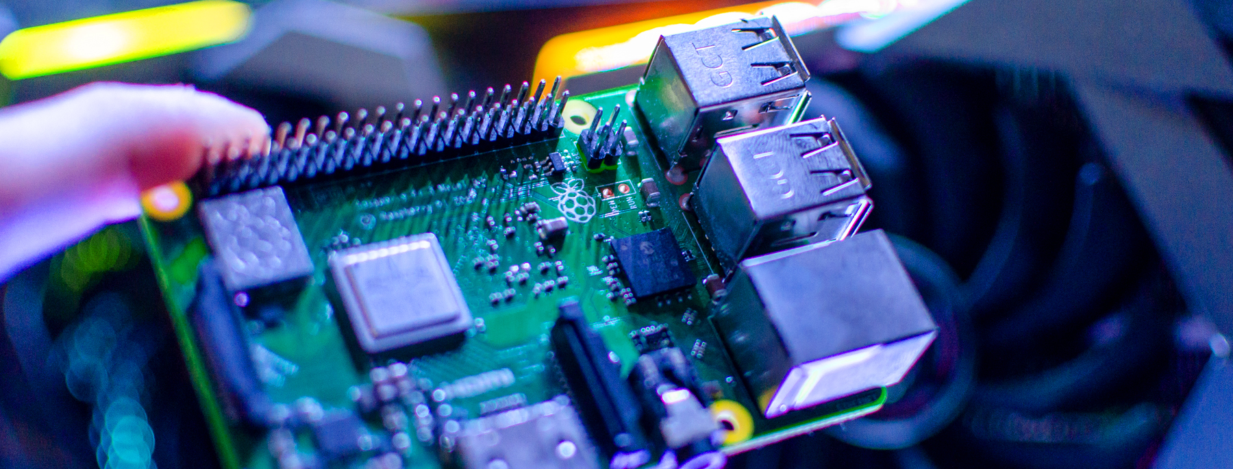
Raspberry Pi is a low cost SBC (single board computer) developed in the United Kingdom by the Raspberry Pi Foundation to promote the teaching of basic computer science in schools and in developing countries.
Because of its low price ($35) and capabilities, it became very popular in markets other than education, such as robotics, research, and more. Now, in its third generation, the Raspberry Pi 3 is packed with a quad-core ARM Cortex-A53 CPU, 1GB of RAM, WiFi, and Bluetooth.
We chose the Raspberry Pi 3 for testing our products because most of our customers use ARM-based platforms, which also made the Raspberry Pi a perfect evaluation board for new customers.
Normally, when using a Raspberry Pi you have to manually flash an image (like the Raspberry Pi OS) on an SD card, and then use the SD card to boot the Raspberry Pi. However, the manual part in this process makes it unusable with our continuous integration (CI /continuous deployment (CD) pipelines. This is one of the reasons why we decided to look for a solution to automate the flashing process. We needed a solution for our CI/CD pipelines and also wanted to give our developers the ability to have a Raspberry Pi with their latest code in a click – no matter where they are located.
Raspberry Pi Boot Process (simplified)
Let’s describe the Raspberry Pi boot process – just to give you a little more background.
It is unique because the first stages of the boot are executed by the GPU (graphics processing unit) and the CPU gets involved very late in this process.
- At power-up, the ARM CPU is offline, but the GPU is powered up.
- The First Stage Bootloader starts executing from the GPU ROM.
- This bootloader tries to mount the SD card and looks for the bootcode.bin (the Second Stage Bootloader) file. If there is no SD card, it tries other sources like USB, network, etc. (out of our scope for now)
- The Second Stage Bootloader (bootcode.bin). This bootloader is responsible for enabling the SDRAM and for the initialization of some peripherals.
- After executing the Second Stage Bootloader, this bootloader looks for the file start.elf,
which is the GPU firmware, loads it to RAM and starts executing it (on the GPU). - The GPU looks for the kernel image (kernel.img) and also loads it to RAM.
- The GPU starts the kernel execution on the ARM CPU.
- The kernel mounts the Root Filesystem from the second partition of the SD card and executes the init process.
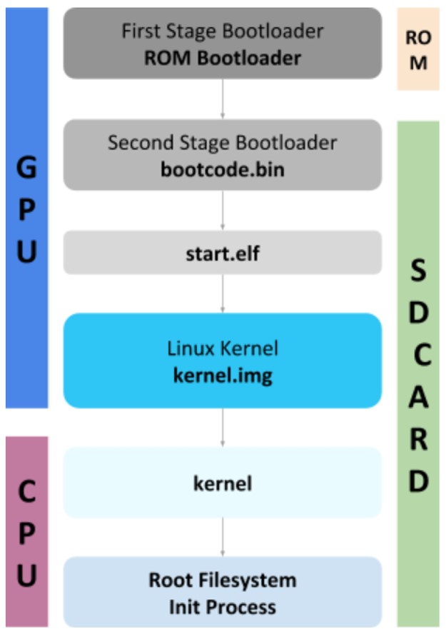
Figure 1: Raspberry Pi Boot Process
Raspberry Pi Image Structure
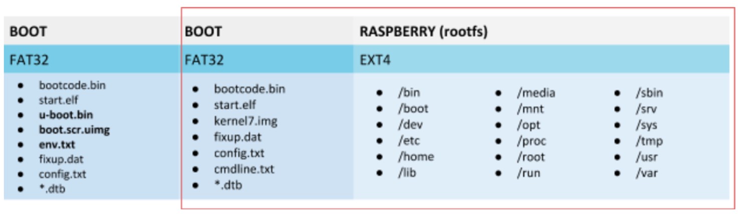
The Raspberry Pi image is divided into two partitions. The first partition is the BOOT partition. All the files we described in the boot process and even more (we simplified the boot process) are located in this partition. The second partition is where the root filesystem (rootfs) is located.
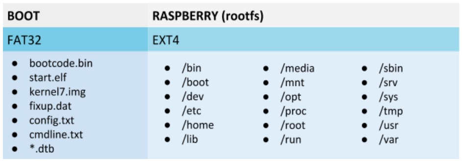
Figure 2: Raspberry Pi Partitions
Remote Flashing – What are the Options?
Before making our own flashing solution, we considered the following three options:
- Network Boot
- SD card Mux
- Linaro Lava
We will cover each of these solutions and the reasons we decided against using them.
Network Boot
With network boot, the GPU fetches all the files needed for boot, which can usually be found on the SD card BOOT partition, from a TFTP server. It then loads and executes the kernel and points the rootfs source to be an NFS server share as seen in Figure 1 below.
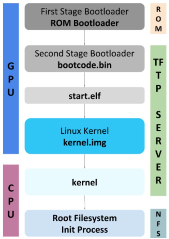
Figure 3: Network Bootloader Process
There are multiple pitfalls with this solution:
- Only one TFTP server can be on a network, so we must create a separate network for our Raspberry Pis.
- We need to extract the content of the image and prepare a different share for each Pi, and a TFTP folder for each Pi.
- This leads to a need for a storage server for all the NFS shares, and fast networking to handle all the requests
Regardless of all the disadvantages listed above, the primary reason that this solution was ruled out is that the filesystem is not local. Our customers require a solution that enables them to store all their files locally.
SD Card Mux
SD card multiplexer is a device that acts as a simple switch for the SD card. The SD card is connected to both Raspberry Pi and a PC in parallel. With the SD Card Mux, we can control which end is active, the SD card or the PC. For flashing the SD card we will select the PC to be the active end, flash the SD card, and then switch the active end to the Raspberry Pi.
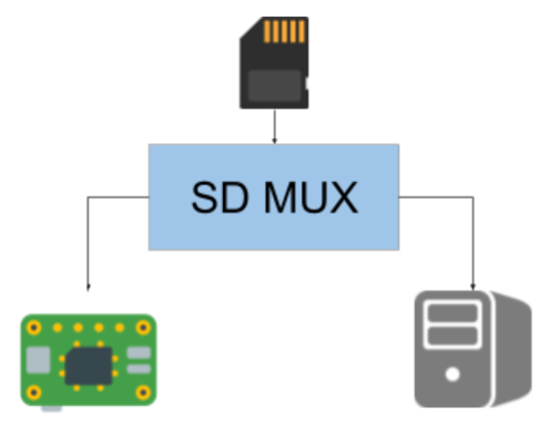
Figure 4: SD Mux Switch Between SD card and Raspberry Pi
We rejected this method because SD Card Mux’s are very expensive, making them inappropriate for a large scale solution.
Linaro Lava
Linaro Lava is a continuous integration system for deploying operating systems onto physical and virtual hardware to run tests. It is very powerful and supports many targets.
However, it is not easy to set up the environment so there is a learning curve involved. In addition, the built-in target for the Raspberry Pi uses network boot, which we already ruled out. Choosing this solution will require making a customized target for Lava so that it is not based on a network booting solution.
Although the scalability of this solution may make it a choice in the future so we didn’t rule it out completely for a large scale project, however, at this time, we decided against it because of the long learning curve and the lack of a matching target.
Our Custom Solution
We needed a solution that is simple, scalable, and can boot from an SD card.
We decided to introduce another bootloader to the system (as if we didn’t have enough :)).
The new bootloader is Das U-Boot (The Universal Bootloader). It is an open-source bootloader for embedded devices that supports most processors and common boards in the market. It can boot from the network, USB, and much more.
U-Boot is not only a bootloader. It can work standalone and add applications to it.
It supports Hush Shell scripts and we use it for the flashing.
Our solution consists of three main blocks:
- Flashing Server
- Recovery Image
- Flashing Scripts
Setting Up the New Bootloader
- We created a new partition at the beginning of the SD card. This partition is very similar to the original partition, which includes the original bootloaders and firmware, but instead of having a kernel image, we’ll include the new bootloader. This bootloader is permanent and not included in the flashed image in order to avoid cases of flashing a corrupted image and bricking the system.Note: If you remember from the boot process explanation, one of the last steps is loading the kernel.img and executing it with the CPU. Whether the firmware loads our bootloader image instead of the kernel.img is not important to the entire operation. However, we will need to configure the change in the Raspberry Pi bootloader configuration file (config.txt).
- We created a template SD image (Recovery Image) with three partitions.
- First partition includes the Raspberry Pi Bootloader, the U-Boot image, and the U-Boot boot script.
- Second and third partitions are placeholders for the real image.
New Boot Process
- When the Raspberry Pi boots up, it loads U-Boot and not the kernel.
- U-Boot loads the boot script, and this is where the flashing happens.
- The boot script reaches out to a TFTP server (Flashing Server), and looks for an image in a folder named by its MAC address. In this way we can send different images to different Raspberry Pi’s
- If it finds an image, it downloads it to the Raspberry Pis RAM, and then writes it to the SD card starting from the second partition (the U-Boot is located at the first partition – we don’t want to overwrite it)
- If it doesn’t find an image, or when the flashing is finished, it continues booting.
- It loads the kernel from the second partition, and the kernel mounts the root filesystem from the third partition.

Figure 5: Raspberry Pi New Partitions
But what about the boot command you ask?
The boot command in the Raspberry Pi is in a file called cmdline.txt that usually sits on the first partition. Our solution places it in the second partition. Of course, we want to use it while booting with U-Boot, but it needs to be modified. The original boot command points to the second partition for the root directory (rootfs partition), which now after flashing is the third partition. - We must modify this value in order to point it to the third partition before booting when using this command.
dwc_otg.lpm_enable=0 console=serial0,115200 root=/dev/mmcblk0p3 rootfstype=ext4 rootwait
This diagram sums up the new boot process:
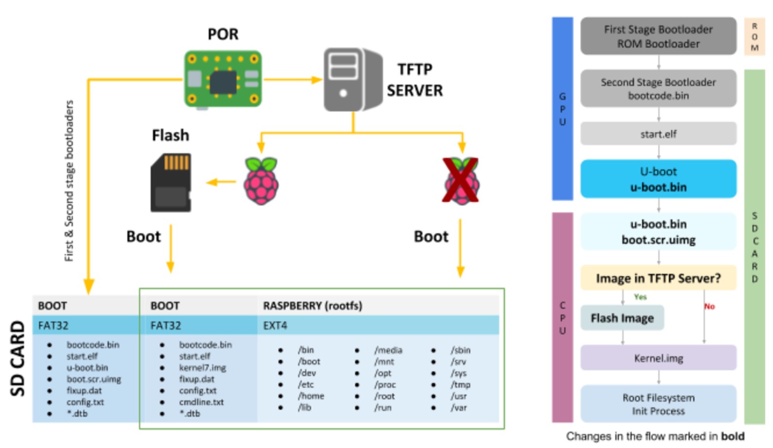
Figure 6: New Boot Sequence
Remote Flashing – Server Side
Now that we have a remote flashing solution, we can use it in our CI/CD pipelines.
We use Jenkins to copy a Raspberry Pi Image to the Flashing Server. It then triggers a Flashing Script on the Flashing Server that places the image in the correct folder.
Flashing Server hard resets target Raspberry Pi (it’s physically connected to the Pis reset).
Target Raspberry Pi boots and looks for an image on the Flashing Server, if there is one – it flashes it on the second and third partitions. It then it loads the kernel from the second partition and boot with rootfs from the third partition
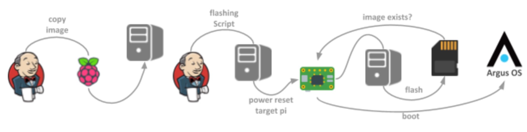
Figure 7: Automated flashing of the Raspberry Pi
Now we have a Raspberry Pi flashed with our latest software, and Jenkins can trigger the automation tests for testing our software on real hardware.
Summary
We resolved the remote flashing challenge by adding another bootloader, U-Boot, to the Raspberry Pi. We also reversed the standard order of booting and flashing, by finding a simple, scalable, and cost-efficient bootloader that can be used locally. This bootloader is permanent and not included in the flashed image (we can update it, but we don’t flash with the new images so that we do not brick the system in the event of a corrupt image).
This bootloader uses a script to fetch the new image from a TFTP server, and then flashes it on the Raspberry Pi SD card. We use Jenkins to automate the flashing of multiple Raspberry Pi’s for testing and developing.
Although we chose U-boot, there are more solutions that might be worth considering when looking for a solution to load a Raspberry Pi system remotely, like the Linaro Lava or native network boot.
If you’re in need of a Raspberry Pi in your CI pipelines and existing solutions seem too complex or too limited, this solution may be right for you! To make your own remote flashing environment, please find instructions and source files here: https://github.com/
Author: Itay Sperling, Embedded Linux Software Developer
at Argus Cyber Security